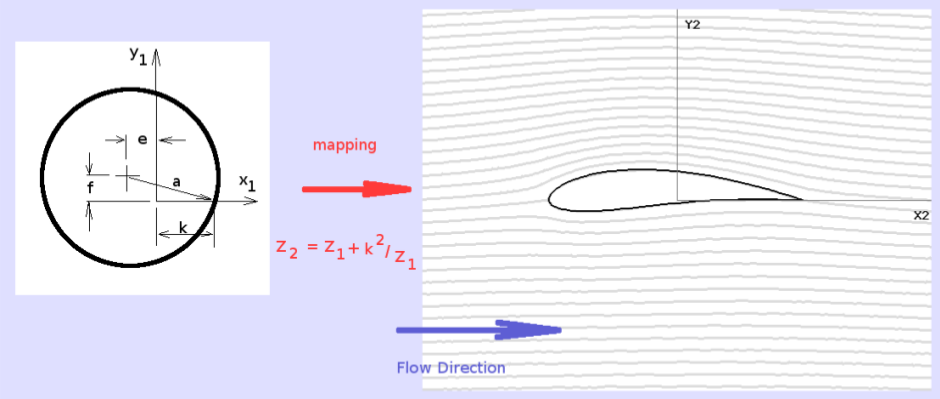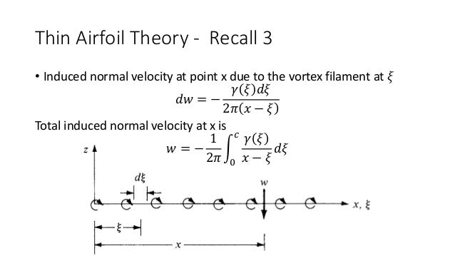


This is detailed in the following 2 plots. A Technique for Rendering Approximate Solutions to Physical Problems Uniformly Valid. Although the use of these derivatives is beyond. Journal of the Aeronautical Sciences Vol. Thin-airfoil theory is a convenient basis for estimation of the important derivatives ( Z q ) and ( M q ). The flow pattern is built up by placing a bound vortex sheet on the camber line and. Leading-Edge Singularities in Thin-Airfoil Theory. However, the roughness effects keeps the measured lift slope around 0.11 for thickness ratios up to 24%. In thin airfoil theory, the airfoil is replaced with its mean camber line. We do the our derivations for a cambered airfoil, and treat thin airfoil as a special situation where the camber line shape Z(x) is zero. Oddly enough, for the smooth NACA 63-series and 64-series, the lift slope will actually increase with increasing thickness ratios. Our book has the derivation for symmetric airfoil first (Section 4.7) followed by cambered airfoil (Section 4.8). The mean-line, y (x), is considered to produce a distribution of vorticity along the line, s. This is all detailed in the plot below from the Theory of Wing Sections (excellent reference text). Thin Airfoil Theory - Simplifications Bernoulli: Kutta Condition: uV cos +u' vV sin +v' x c V(c,0 +) V(c,0-) y Assumptions: 1. The airfoil is modeled as a thin lifting mean-line (camber line). The thin airfoil theory will predict a finite wing lift slope of $2\pi$ rad$^$ near thickness ratios of 24%. $a_0$ is left in the above equation so one can predict the elliptical finite wing lift slope (effects of aspect ratio), $a$, given the best predicted/measured infinite wing lift slope $a_0$.

That is because airfoils are not actually infinitely thin in practice, and will deviate from thin airfoil theory by a small amount. In class we showed that the local pressure coefficient is given by (using small disturbance assumptions). thin airfoil theory based on approximate solution of the transonic flow equation A method is presented for the approximate solution of the nonlinear. A comparison of theoretical and experimental lift and drag for a cavitating hydrofoil shows good agreement until the theoretical cavity closure nears the trailing edge.In general, most airfoils only approximately display the $2\pi$ lift slope as predicted by thin airfoil theory. Four related integrals involving the wetted-surface contour slope distribution lead to drag, lift, cavity pressure and α + vs cavity length. Next we look at the lift results from thin airfoil theory. The lift must be way different between thin airfoil theory. 1, lets look at the lift curve comparison.
#Thin airfoil theory plus
The general solution for given wetted-surface profile, cavity length and particular cavity termination is constructed by superposition of the profile's cusp-closure solution (angle of attack α +) plus the particular flat-plate solution to give the desired angle of attack α. Thin airfoil theory is a simple theory of airfoils that relates angle of attack to lift for incompressible, inviscid flows. The thin airfoil theory is pretty good, but underestimates the pressures slightly from about 10 to 50 of the chord. The basic premise of the theory is that for an airfoil in a uniform flow V, the airfoil can be replaced by a vortex sheet along. Cavity-termination models employed are the closed, the partly closed and the open models for which the thickness of the implied ’wake’ following the cavity ranges from zero to maximum for the open model. Thin-airfoil theory is applied to steady, plane potential flow about vented or cavitating hydrofoils of arbitrary profile when there are two free-streamlines detaching from the foil and bounding the single cavity that extends downstream of the trailing edge.


 0 kommentar(er)
